Field Termination vs. Fusion Splicing: A Contractor's Decision Guide
Every fiber optic installation eventually arrives at the same decision point: terminate in the field or fusion splice. The answer affects insertion loss, labor cost, required skill level, equipment investment, and long-term reliability. Getting it wrong means either spending $15,000 on a fusion splicer you did not need or accumulating connector losses that blow through your link budget and cause intermittent failures on cameras three buildings away.
This guide is written for low-voltage contractors who install fiber for security systems, not for telecommunications carriers with unlimited budgets and dedicated splicing crews. We will compare mechanical field termination and fusion splicing across every dimension that matters on a security project, cover connector types, explain when pre-terminated assemblies are the smarter choice, and provide the loss budget math you need to make a defensible engineering decision.
Connector Types in Security Installations
Before comparing termination methods, you need to understand the connectors you will encounter. The security industry has largely standardized on two form factors, with a third emerging for high-density applications.
- SC (Subscriber Connector). The workhorse of security fiber installations. 2.5 mm ferrule with a push-pull latching mechanism. Common on media converters, older switches, and NVRs. Duplex SC is standard for most point-to-point camera backbone links. Available in UPC (blue) and APC (green) polish. For security infrastructure, UPC is the default unless you are connecting to GPON or carrier equipment that specifies APC.
- LC (Lucent Connector). Half the size of SC with a 1.25 mm ferrule and a retention clip similar to an RJ-45. LC has become the dominant connector on modern SFP and SFP+ transceivers, enterprise switches, and current-generation NVRs. If you are installing fiber for a new system today, LC is almost certainly what the equipment requires. Duplex LC is standard; the smaller form factor allows higher port density on patch panels.
- MPO/MTP (Multi-fiber Push On). A high-density connector carrying 8, 12, or 24 fibers in a single ferrule. Used primarily for trunk cables in structured cabling systems and data center interconnects. You will encounter MPO/MTP in large security operations centers (SOCs) or campus backbone links where fiber counts exceed 24 strands. Polarity management is critical: TIA-568 defines three methods (A, B, C) and mismatched polarity is the most common cause of MPO link failures.
Mechanical Field Termination
Mechanical field connectors contain a factory-polished, pre-cleaved fiber stub inside the connector body. The installer strips the cable, cleaves the field fiber, and inserts it into the connector where it butts against the factory stub. A mechanical cam, wedge, or crimp holds the fibers in alignment. No adhesive, no curing, no polishing. The connector is ready to test within minutes.
The major products in this category are the Corning UniCam, Corning OptiSnap, and 3M NPC (No-Polish Connector). Each uses a slightly different alignment mechanism, but the general workflow is identical: strip, clean, cleave, insert, cam. The tool investment is modest, typically $1,500 to $3,000 for a complete field termination kit including the cleaver, visual fault locator (VFL), and connector installation tools.
The tradeoff is insertion loss. A well-executed mechanical termination yields 0.3 to 0.5 dB per connector, with the manufacturer specification typically rating 0.5 dB maximum. In practice, a skilled installer averages about 0.3 dB. A less experienced technician may see 0.5 to 0.75 dB, particularly on single-mode fiber where the 9-micron core demands more precise alignment than multimode's 50-micron core.
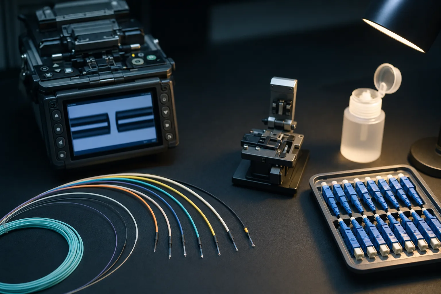
Fusion Splicing
Fusion splicing uses an electric arc to melt two bare fiber ends and fuse them into a continuous glass path. The result is a permanent joint with typical loss of 0.02 to 0.05 dB, roughly an order of magnitude better than a mechanical connector. When combined with a pigtail (a short length of fiber with a factory-polished connector on one end and a bare fiber on the other), fusion splicing provides the lowest possible loss while still presenting a connectorized interface at the patch panel.
Modern core-alignment fusion splicers (Fujikura 90S+, Sumitomo T-72C+, INNO View 7+) use cameras and motors to actively align the fiber cores before firing the arc. These machines achieve consistent splice losses below 0.03 dB on single-mode fiber. Ribbon splicers can fuse 12 fibers simultaneously, which is essential for high-count cables. The equipment investment is significant: a quality core-alignment splicer costs $8,000 to $18,000, plus $2,000 to $4,000 for a precision cleaver.
The learning curve is actually lower than many contractors assume. A modern splicer automates core alignment, arc calibration, and splice loss estimation. After a day of manufacturer training and 50 practice splices, most technicians are producing consistent sub-0.05 dB splices. The real skill is in fiber preparation: proper stripping, cleaning with 99% IPA, and a clean cleave with an angle below 1 degree are prerequisites for a good splice.
Termination Method Comparison
| Attribute | Mechanical Field Term | Fusion Splice + Pigtail | Pre-Terminated Assembly |
|---|---|---|---|
| Typical Loss per Connection | 0.3 - 0.5 dB | 0.02 - 0.05 dB (splice) + 0.2 dB (pigtail connector) | 0.2 - 0.35 dB |
| Equipment Cost | $1,500 - $3,000 | $10,000 - $22,000 | $0 (none required) |
| Per-Connector Material Cost | $8 - $25 | $3 - $8 (pigtail + splice protector) | $15 - $40 (amortized) |
| Time per Termination | 3 - 5 minutes | 5 - 8 minutes | Pull and patch (minutes) |
| Skill Level Required | Moderate (1-day training) | Moderate-High (1-2 day training + practice) | Low (pull cable, plug in) |
| Single-Mode Performance | Acceptable with practice | Excellent | Excellent (factory tested) |
| Multimode Performance | Good | Excellent | Excellent |
| Best For | Small jobs, repairs, <24 terminations | High fiber counts, single-mode, long runs | Structured cabling, data centers, tight schedules |
Loss Budget Math: Why It Matters
A fiber link budget is the maximum allowable optical loss between a transmitter and receiver. Exceed it and the link fails. A typical 1000BASE-LX single-mode SFP has a link budget of 5.0 dB over 10 km. A 10GBASE-LR SFP+ has approximately 6.2 dB over 10 km. These numbers seem generous until you start adding connectors and splices.
Consider a campus security backbone: a 2 km single-mode run from the main IDF to a remote building IDF. The link includes two patch panel connections at each end (4 mated connector pairs), one intermediate splice point where the cable enters a building, and the fiber attenuation itself. Single-mode fiber (OS2) attenuates at approximately 0.35 dB/km at 1310 nm.
With mechanical field termination at 0.5 dB per mated pair: (4 x 0.5) + (1 x 0.05) + (2 x 0.35) = 2.0 + 0.05 + 0.7 = 2.75 dB. That is within the 5.0 dB budget with margin to spare. But add two more connector pairs for a mid-span patch point, and you are at 3.75 dB. Now factor in connector aging, contamination, and temperature effects (add 1-2 dB of margin per TIA-568 recommendations), and you are pushing the limit. The same link with fusion-spliced pigtails at 0.25 dB per mated pair: (4 x 0.25) + (1 x 0.03) + (2 x 0.35) = 1.0 + 0.03 + 0.7 = 1.73 dB. That additional 1.0 dB of margin can be the difference between a reliable link and an intermittent one.
When to Choose Pre-Terminated Trunk Cables
For structured cabling runs between telecom rooms where the route is known and cable lengths can be measured in advance, pre-terminated trunk cables (factory assemblies with connectors on both ends) offer the best combination of low loss, fast installation, and guaranteed performance. They are factory tested to IL < 0.2 dB per connector and come with a test report. The premium over bulk cable plus field termination is typically 15-25%, but you save all labor time, eliminate field termination risk, and get a warranted product. For security projects with tight commissioning schedules, pre-terminated trunks are often the fastest path to a working backbone.
OTDR Testing and Inspection
An Optical Time Domain Reflectometer (OTDR) sends calibrated light pulses down a fiber and analyzes the backscattered returns to create a trace showing every event along the link: connectors, splices, bends, and breaks. Every fiber link should be OTDR-tested from both ends (bidirectional testing per TIA-526-7) to catch directional events that may be invisible from one end.
When reading an OTDR trace, connectors appear as reflective events (a spike above the backscatter baseline) with associated insertion loss. A good mechanical connector shows 0.3-0.5 dB of loss and moderate reflectance. A fusion splice appears as a non-reflective event (a step down in the trace with no spike) showing 0.02-0.05 dB of loss. If you see a reflective event at a splice point, the splice is cracked or contaminated and must be redone.
Before any testing, inspect every connector endface with a fiber inspection microscope at 200x or 400x magnification. IEC 61300-3-35 defines pass/fail criteria for endface cleanliness: no defects larger than 10 microns in the core zone, no defects larger than 25 microns in the cladding zone, and no scratches crossing the core. A contaminated connector will fail a loss test even if the termination itself is perfect. Always clean with a one-click cleaner or lint-free wipes with IPA before mating.
Fiber Count Planning for Future Growth
The incremental cost of additional fibers in a cable pull is trivial compared to the cost of pulling a second cable later. A 12-strand single-mode cable costs approximately 15-20% more than a 6-strand in the same jacket. A 24-strand costs roughly 30% more than a 12-strand. The labor to pull any of these cables is identical because the outer diameter difference is negligible.
For security backbone installations, our standard recommendation is to install a minimum of 12-strand single-mode (OS2) cable even if the immediate requirement is only 2 strands. A campus with IP cameras today will likely need additional bandwidth for video analytics, access control, intercom, and IoT sensors within the cable's 25-year lifespan. The six dark fibers you install today cost almost nothing; the emergency cable pull you avoid in five years saves thousands.
Conclusion
The field termination versus fusion splicing decision is not ideological. It is an engineering calculation based on fiber count, single-mode versus multimode, link budget, project scale, and the team's equipment and skill set. For a 4-camera remote building with multimode fiber and 6 terminations, mechanical field connectors are the efficient choice. For a 200-camera campus backbone on single-mode with 96 or more terminations, a fusion splicer pays for itself on the first project. For structured cabling between telecom rooms with known distances, pre-terminated trunks offer guaranteed performance with zero field termination risk.
Zimy Electronics provides fiber design, installation, and testing services for security infrastructure projects of every scale. Our certified fiber technicians are equipped with both mechanical termination kits and core-alignment fusion splicers, and we select the right method for each project based on the engineering requirements rather than defaulting to whatever tool is on the truck. From single-building camera runs to multi-building campus backbones, we deliver tested, documented, and warranted fiber infrastructure that meets TIA-568 and BICSI standards.